Global reach throughout the Internet is the primary goal of network and infrastructure engineers. Although satellite systems are utilized for specialized applications, the global Internet depends almost entirely on subsea fiber-optic cable networks for intercontinental data exchange. These cables are critical assets for carriers, Service Providers, Content Providers (OTTs), and research networks worldwide.
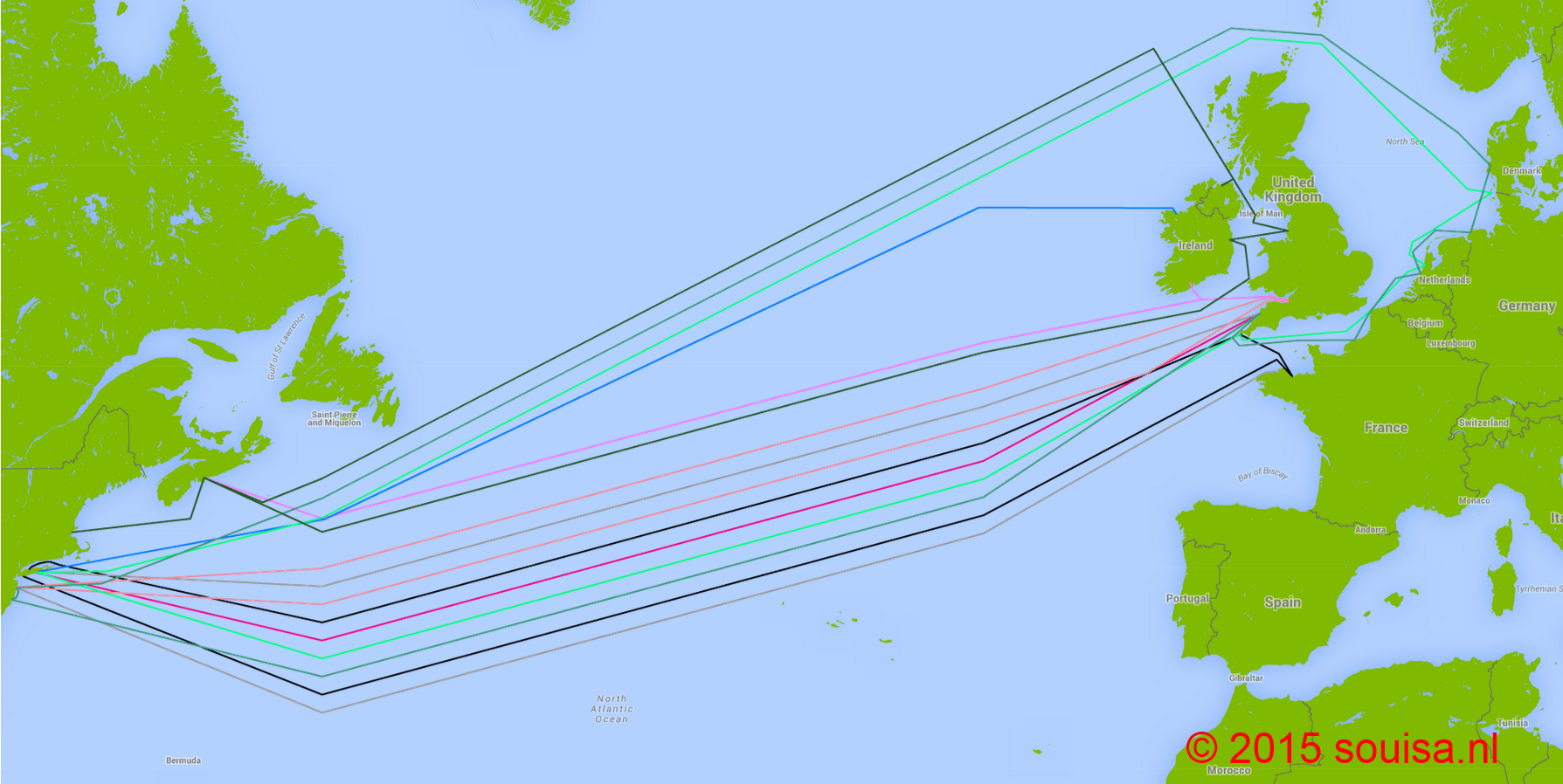
Today, the transatlantic subsea market is served by 7 major cable systems, comprising 13 distinct cables (Figure 1):
-
Atlantic Crossing-1 (AC-1) – 2 main cables owned by Level 3
-
Yellow – Single cable system owned by Level 3
-
FLAG Atlantic-1 (FA-1) – 2 cables owned by Global Cloud Xchange
-
Hibernia Atlantic – 2 cables owned by Hibernia Networks
-
TAT-14 – 2 cables owned by an international operator consortium
-
TGN-Atlantic – 2 cables owned by Tata Communications
-
Apollo – 2 cables owned by Vodafone / Alcatel-Lucent
Threats & Subsea Fault Repair Realities
When network engineers evaluate high-capacity 100 Gbps architectures between the United States and Europe, the primary mandate is guaranteeing robustness across multiple underlying links—ensuring that if a cable fault occurs, sufficient redundant capacity absorbs traffic without service disruption.
A resilient network design typical leases capacity across three or four separate submarine systems. However, subsea infrastructure remains constantly exposed to external hazards, including commercial fishing operations, ship anchors, underwater landslides, and seismic activity. Commercial ship anchors cause the vast majority of shallow-water cable cuts near coastlines. Even though coastal cables feature heavy metallic armoring and are jet-buried up to a meter into the seabed, heavy anchors dropped by supertankers during Atlantic storms easily sever fiber optic bundles.
The critical differentiator is repair time. Terrestrial fiber outages can usually be dispatched to field engineers within 4 hours and restored within hours or a couple of days. Conversely, repairing a deep-sea cable break requires mobilizing specialized cable repair ships, locating the fault site via optical time-domain reflectometers (OTDR), grappling the cable, and performing fusion splices in cleanroom facilities on deck. This process routinely takes several weeks—further extended by ocean weather conditions and limited ship availability worldwide.
The architectural challenge is identifying three or four cables that follow physically distinct paths with minimal route overlap to avoid simultaneous multi-cable failure.
Pre-2015 Transatlantic Routing Strategies
Until mid-2015, high-availability architecture relied on combining the Hibernia Atlantic North cable (connecting Canada to the UK) with Apollo South (connecting US to France).
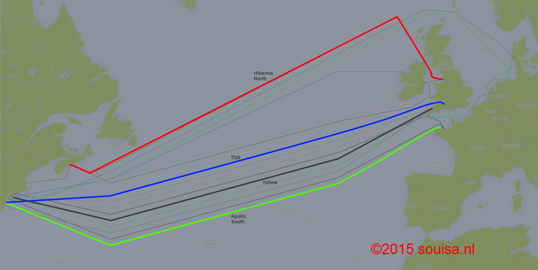
By landing directly on continental Europe, Apollo South effectively bypasses the London interconnect hub—preventing Greater London from serving as a single point of failure for international networks. For low-latency requirements, capacity was layered across Level 3's Yellow and Tata's TGN Atlantic systems. While protecting against equipment failures at individual Cable Landing Stations (CLS), Yellow and TGN shared common terrestrial backhaul routes in the UK, making Apollo South essential for offloading and restoration.
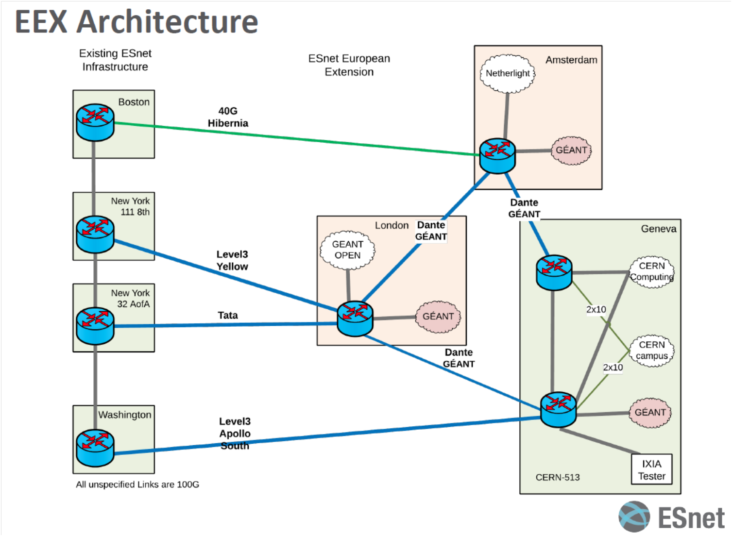
A notable implementation was the Energy Sciences Network (ESnet) European extension to connect US research centers with European facilities (including DANTE and CERN/LHC). ESnet deployed 100G waves across Yellow, TGN, and Apollo South, complemented by a 40G circuit on Hibernia Atlantic into Amsterdam.
Physical Cable Crossing Risk Analysis
Before laying subsea cable, owners must secure formal crossing agreements from operators of existing systems. High concentrations of physical cable crossings in coastal waters increase vulnerability to localized anchor drags or dredging activity.
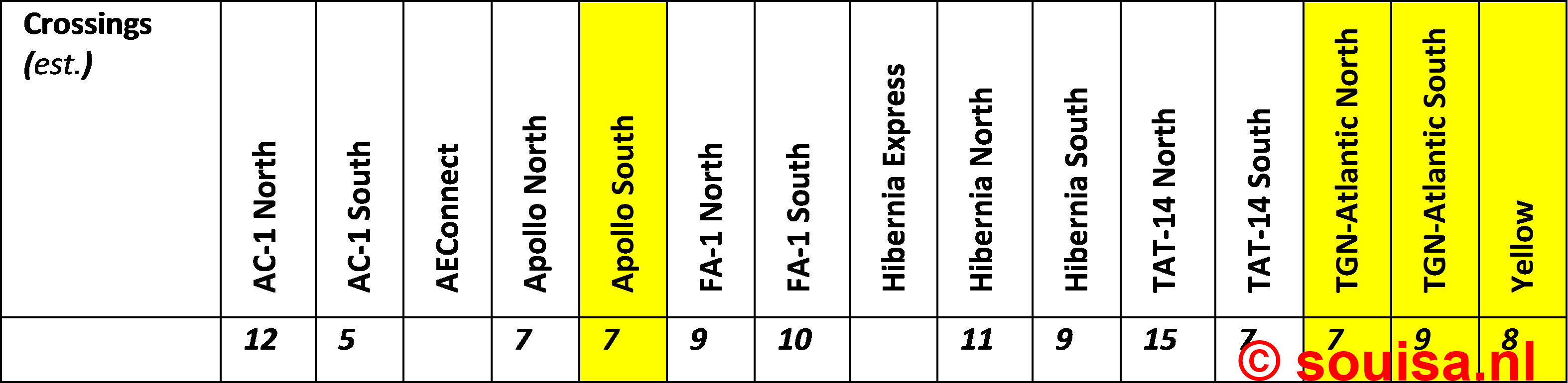
Spatial analysis reveals that systems traversing the Eurasian shelf intersect frequently near coastal approach corridors, requiring careful route planning when selecting redundant pairs.
Next-Gen Capacity: AEConnect & Hibernia Express
The deployment of Hibernia Express and AEConnect introduced high-capacity 100G coherent optical technology to the transatlantic route, triggering price compression and capacity expansion.
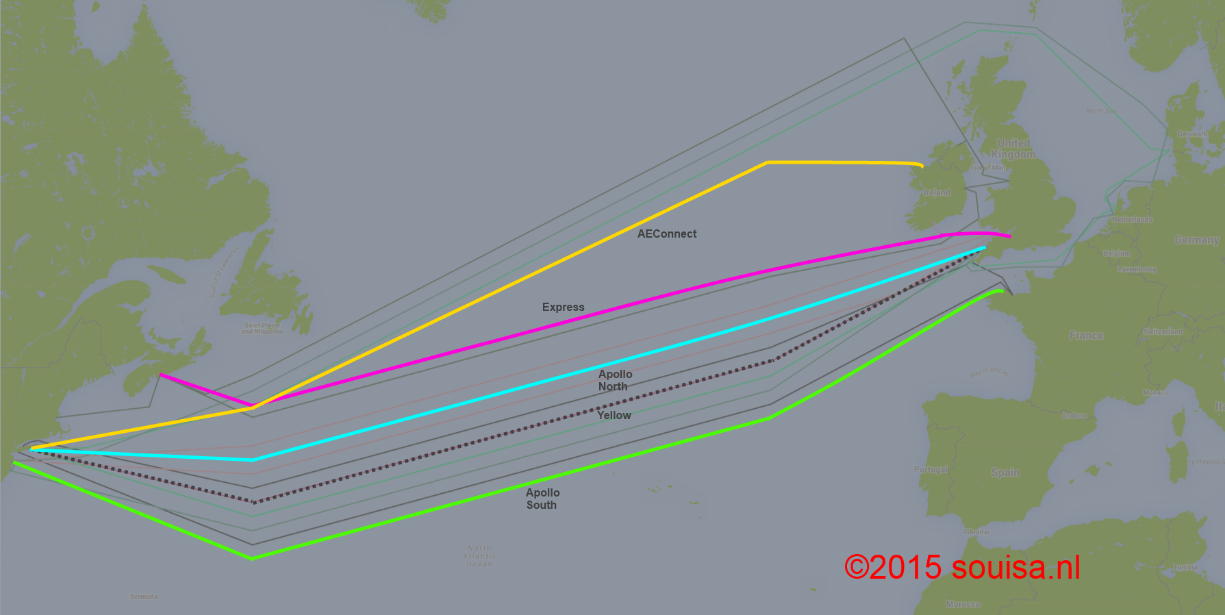
AEConnect offered a direct replacement for aging legacy cables, enabling backhaul routes that bypass London directly into Amsterdam. However, because Hibernia Express, Apollo North, and Yellow share terrestrial backhaul segments in the UK and Long Island, combining them requires strict diversity auditing to avoid shared conduit failures.
Ultimate Resilience Architecture
For maximum resilience, networks can terminate Hibernia Express at the Cork CLS in Ireland rather than Brean in the UK, creating spatial separation from mainland British landing zones.
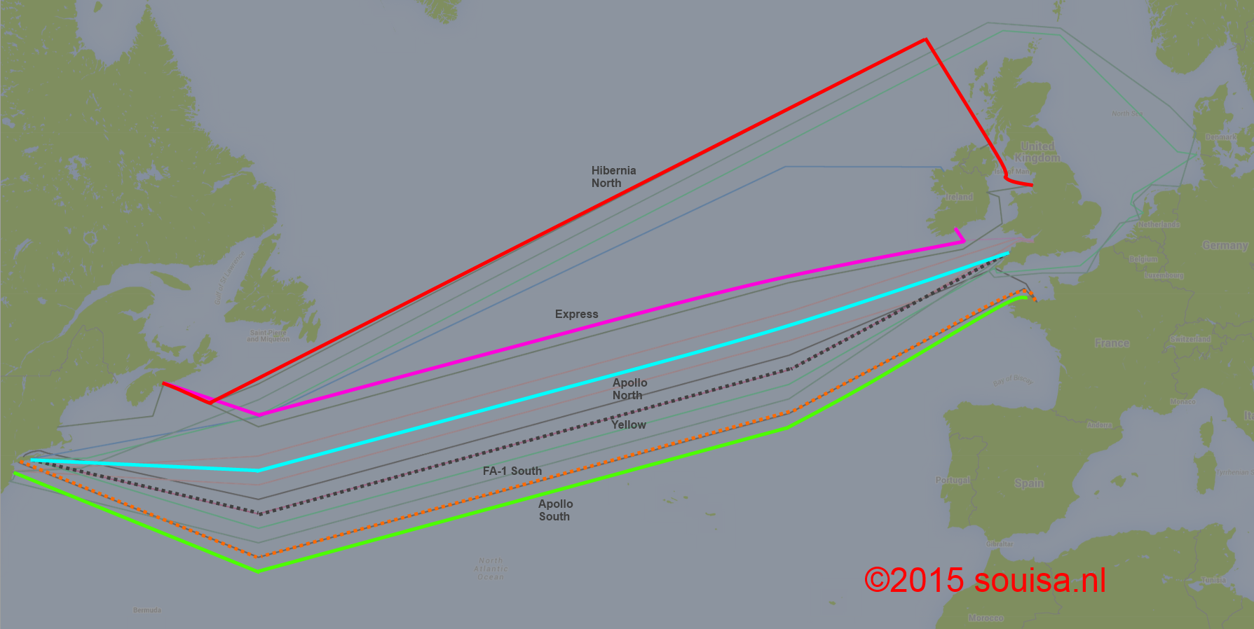
Combined with diverse terrestrial backhaul from Cork to Dublin, London, and Amsterdam, this model isolates the network from physical outages in southern UK or New York landing clusters. Layering capacity on Apollo South or FA-1 South completes the four-path framework into mainland Europe.
Ashburn Data Center Corridor Strategies
Network architects building connectivity for Ashburn, Virginia data center clusters face a historical limitation: legacy transatlantic subsea cables land exclusively in New York or New Jersey.
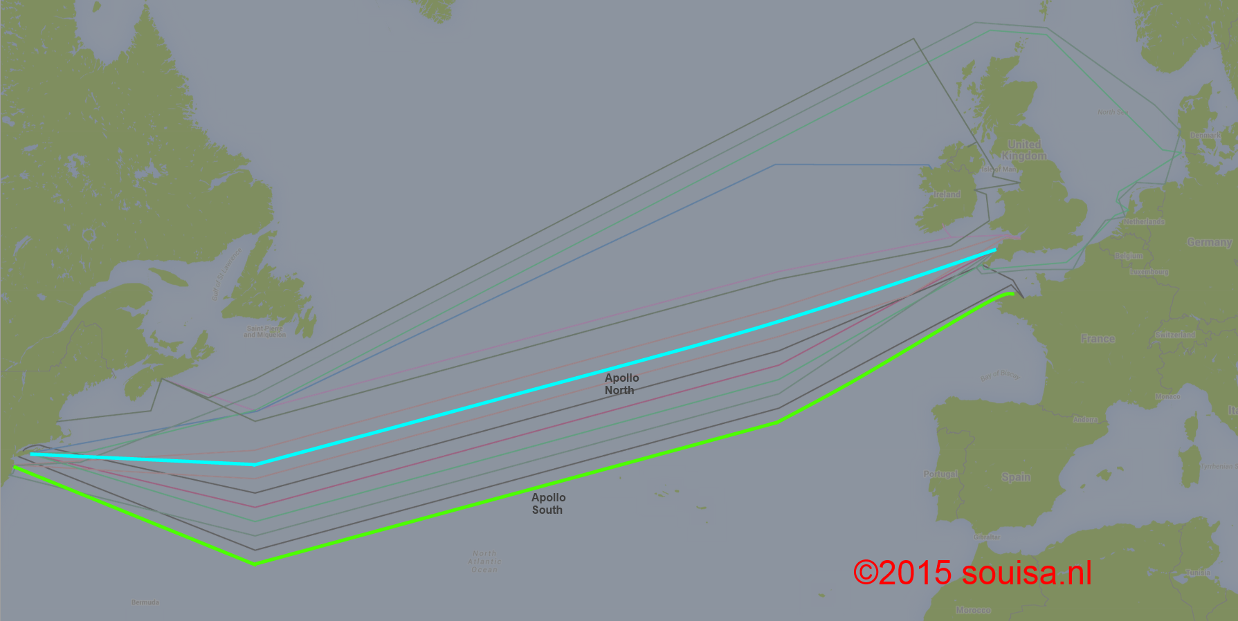
Utilizing both Apollo North and Apollo South provides the shortest physical backhaul path to Ashburn while maintaining route diversity via New York transit points.
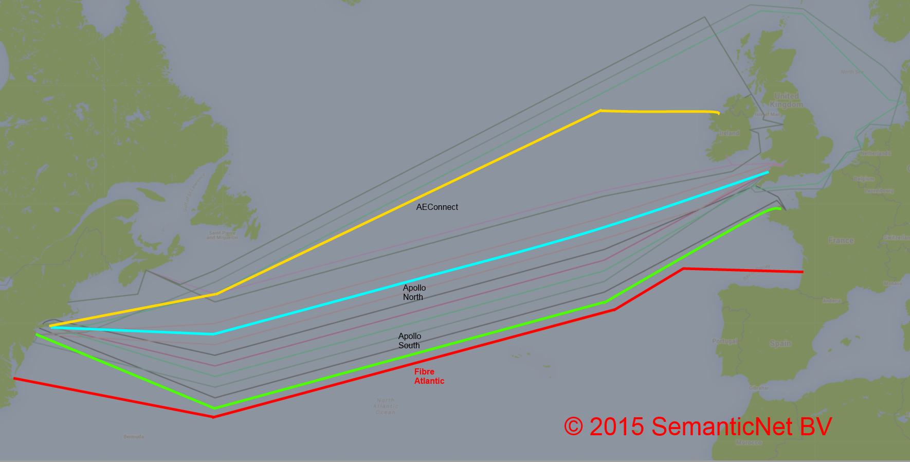
Adding AEConnect enhances path diversity, though it shares Long Island backhaul corridors with Apollo North. Where Apollo access is constrained, FA-1 or TGN Atlantic serve as effective secondary options.
Opening a New Corridor: Fibre Atlantic
To eliminate dependence on congested New York and London hubs, the Fibre Atlantic initiative was conceived by SemanticNet to establish a dedicated mid-Atlantic subsea corridor.
By connecting Virginia Beach directly to France, Fibre Atlantic establishes a physically isolated subsea track south of legacy Atlantic cables—delivering direct, low-latency interconnection between Ashburn, Virginia and European data center hubs in Paris, Frankfurt, Amsterdam, and Marseille.